Starfish PRO
  Features
  Imaging Performance
  Image Sensor Support
  Packaging
  Software Support
  Spec Sheet
  Models
  Starfish PRO FAQ
 Ordering Information
  Starfish PRO 4M-M
  Starfish PRO 4M-C
   

 Starfish
  More Information
 Ordering Information
  Starfish Standard
  Starfish Guider


Image quality produced by a given camera is what matters. This is, after all, the primary purpose of a camera. You use your camera to take a picture of a given scene or object and you want the resulting image to be of the highest quality possible.

Modern day cameras are complex instruments and they are constructed of many different components. In its simplest terms, a camera can be described as an image sensor surrounded by electronics that support the operation of the image sensor chip. The image sensor is used to capture light photons and convert them into an electrical charge that can be later read out by the rest of the camera’s electronic elements. The sole function of the camera electronics, then, is to facilitate the retrieval of the image that the sensor has captured. This is how the above myth was born.

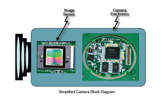
Well, in a perfect world, the above would be true. However, we all know that nothing is perfect in this world and there are degrees to which perfection can be achieved. The reality is that the camera electronics can degrade the quality of an image captured by a CCD image sensor if it is not designed properly. The degree to which the camera’s electronics can accomplish the goal of preserving the fidelity of a captured image after readout from the image sensor is what distinguishes the cameras from manufacturers.

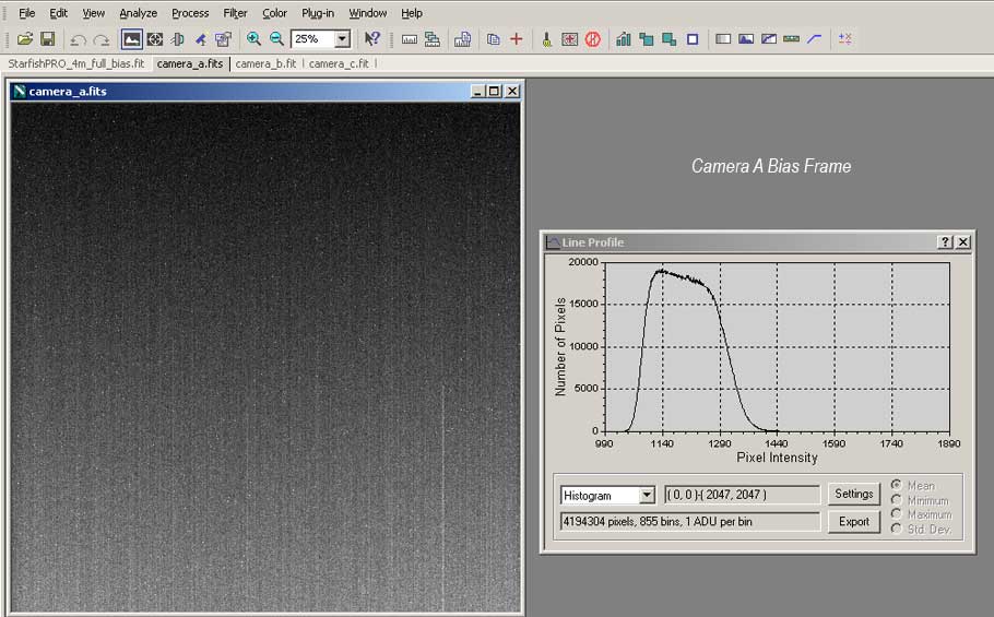
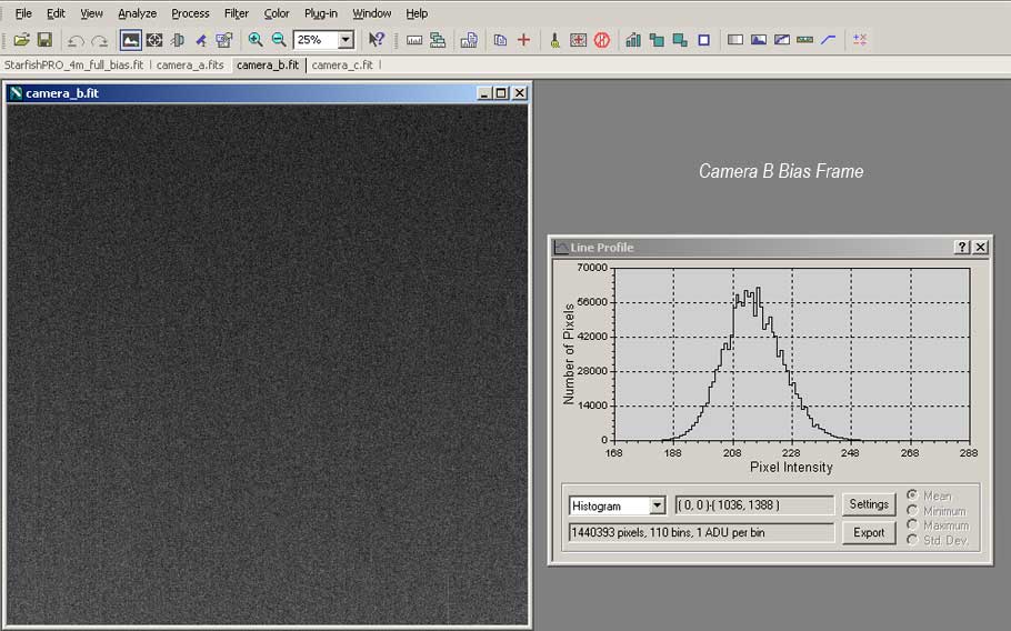
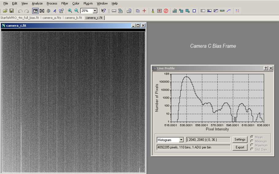
There are many different tests that can be run on a camera to determine various aspects of its imaging performance. Bias frame analysis is one of these tests. Bias frames are dark frames taken with the camera’s shortest exposure setting. Either the camera’s front is covered or its shutter is closed when taking a Bias frame. No light should have hit the camera’s image sensor during the Bias frame exposure. Analysis of a camera’s Bias frame is a good way of evaluating key parameters of a camera’s performance such as readout noise and pixel defects.

Below we have bias frames from four different brands of cameras that all use the same image sensor chip. In this case it is the KAI-04022 CCD chip from Kodak. As you can see there are a lot of differences between the images from the cameras. From this you can see that the above myth is disproved. If the myth was true, then all four Bias frames would look nearly identical since all four cameras use the same image sensor chip.


The Starfish PRO Bias Frame looks very nearly ideal. The image histogram shows a Gaussian distribution when plotted on a linear scale. The pixels show a random ordering of pixel intensities around a mean with no pronounced image artifacts like column intensity offsets.

Camera A shows a more pronounced background intensity gradient getting lighter from top to bottom. Noticeable column offsets are seen, and the histogram plot shows a flattened top with a fairly broad pixel distribution.

Camera B, at first glance, has a very good looking Bias Frame. The image is fairly homogeneous with no significant image artifacts visible. However, the histogram plot shows a deviation from the true Gaussian distribution we would expect. Adjacent pixel bins in the histogram have markedly different pixel counts.

Camera C has an awful looking Bias Frame. Even without looking at the image histogram you can see severe column offsets and image artifacts. The image histogram shows no resemblance to a Gaussian distribution.

Click on the above Bias frame pictures to see a full size image.

 
A key way of getting the lowest read noise in a camera's images, is to lower the readout speed of the pixels from the image sensor. Camera manufacturers know this and, for demanding applications like astro-photography, they design their cameras to readout the CCD image sensor very slowly. Readout speeds of 400KHz and even lower are not uncommon. The downside of this is that it takes a long time to download an image from the sensor. Especially for the larger format image sensors. At a 400KHz readout rate, it would take over 20 seconds to readout an image from an 8Mpixel image sensor.

While this may not pose a significant problem when capturing images with exposure times of 10 minutes or more it makes for very tedious operation when trying to focus your optics and can be very inefficient when doing planetary imaging or lunar photography.

This is one example where the Starfish PRO was designed with usability in mind. We've included the ability to vary the CCD readout speed over a range of from 200KHz to over 12MHz. This makes it possible to give nearly real-time feedback when focusing your camera. Then, you can switch to a slower readout speed to get the lowest possible read noise for your long exposure images.

 
All CCD based cameras have to convert the analog output of the image sensor to a digital value at some point in the signal chain. This is done using A/D converter chips that sample the analog pixel value and produce a digital number representing the pixel's intensity. Many different A/D converters are available to camera designers and the choice of the best one to use is not a trivial exercise. Performance specifications have to be weighed relative to required system performance and cost goals.

For the Starfish PRO design, we selected an A/D converter with some of the best performance specifications in the industry. To help illustrate the point, we compare a couple of key specs between the A/D converter chip used in the Starfish PRO camera and the A/D converter used by some of our competitors. The two specifications we will compare are the INL and DNL. The definition of these specs are:

INTEGRAL NONLINEARITY (INL)
Integral nonlinearity error refers to the deviation of each individual code from a line drawn from “zero scale” through “positive full scale.” The point used as “zero scale” occurs 1/2 LSB before the first code transition. “Positive full scale” is defined as a level 1 1/2 LSB beyond the last code transition. The deviation is measured from the middle of each particular code to the true straight line.

DIFFERENTIAL NONLINEARITY (DNL)
An ideal ADC exhibits code transitions that are exactly 1 LSB apart. DNL is the deviation from this ideal value. Thus every code must have a finite width.

The Starfish PRO uses a Linear Technology LTC2206 A/D converter. The Analog Devices AD9826 is an A/D converter that is widely used by our competitors in their CCD cameras.

In the above charts you can see a dramatic difference between the two A/D converters. Note the deviation from the ideal straight line in the INL charts. Note the difference in scale on the Y-Axis. The converter used in the Starfish PRO deviates less than 1 LSB from the ideal straight line while the competitor's A/D converter can be off as much as 15 counts from the ideal line. That is akin to throwing out 4 LSBs of a 16 bit A/D converter chipʼs range. The DNL charts also show dramatic performance differences.

By the way, the performance differences are not at all unexpected since the AD9826 converter was designed over 10 years ago while the LTC2206 is a modern converter design. The old saying “you get what you pay for” holds true for A/D converters. The LTC2206 cost $69.04 while the AD9826 can be purchased for $9.40. Which A/D chip would you want to have in your camera?

 
Cooling is a very important design aspect of long-exposure CCD based cameras. As exposure times are increased, the dark current accumulating in the pixels of the image sensor can build up to unacceptable levels. One way to mitigate the affects of sensor dark current is to cool the image sensor.

The Starfish PRO camera does this with a two-stage TEC cooler that is mated to a heat sink that is an integral part of the CCD sensor mounting mechanism of the camera. The heat sink becomes the backside of a sealed chamber that houses the CCD chip. Mounted on the top of the chamber is a metal cover that includes a 2-side AR coated glass window that completes the seal. This allows for efficient thermal transfer on both sides of the TEC cooler as well as providing a seal to prevent moisture condensation on the image sensor when cooled. A desiccant capsule is placed within the chamber to absorb any latent moisture in the chamber over time.

Cooling of the heat sink is assisted by a forced-air cooling fan mounted an the heat sink's backside. A high-quality, ball bearing, fan is used to minimize any vibration.

All of this allows us to achieve -30 Degrees C cooling from ambient. Of course the cooling is regulated and the target temperature is user settable via software.


Copyright © 2009. All rights reserved.