|
|
| |
| Introduction: |
| |
The Starfish camera was originally designed as an auto-guider camera for astrophography uses. Since there are several other fine auto-guider cameras on the market today, we frequently get questions about how the Starfish camera compares to our competitor's offerings.
We are not trying to disparage any of our competitors with this comparison. On the contrary, all of the cameras we compared are fine instruments and should serve their user's well. We only wish to point out some of the qualities that make the Starfish camera stand apart from the other cameras. We have tried to be as objective as possible in our tests.
All of these cameras are capable of being used as an auto-guider. However, some of them have been simply pressed into service and were not originally intended to be used in this capacity. For instance, some cameras do not have an integrated guide port and may require additional hardware to be purchased by the user. Others only have USB 1.1 interfaces that have very slow image upload speeds that may hinder performance. |
|
| |
|
|
| Test Methodology: |
|
| |
We tried to keep the support equipment and environment variables constant in our tests. Only varying the camera itself for the comparison pictures. For instance, we used a common optical train and telescope mount for the tests. We also used MaximDL as our image capture application since all of the cameras we tested were supported by this application. We used the latest camera drivers available at the time the tests were run. Lastly, we used the Delta2 Lyrae star field in all of the test pictures.
The following equipment was used in our test setup: |
|
| |
Telescope: |
|
Takahashi FSQ |
|
|
| |
Mount: |
|
Astro Physics AP1200 |
|
|
| |
Camera Control Application: |
|
MaxIm DL 4.59 |
|
|
| |
Laptop: |
|
MacBook PRO (Intel Core Duo CPU @2GHz, 2Gbyte RAM) |
|
| |
Operating System: |
|
Windows XP |
|
|
| |
Star Field: |
|
Delta2 Lyrae |
|
|
| |
|
|
|
|
|
|
| Test Cameras: |
|
| |
The following cameras were used during our tests: |
|
|
| |
|
|
Relevant specifications of these cameras: |
| |
Camera: |
Starfish |
CamA |
CamB |
CamC |
CamD |
CamE |
| |
Image Sensor: |
MT9M001 |
MT9M001 |
ICX254AL |
ICX424AL |
KAC-9619 |
KAF-0402ME |
| |
Array Format: |
1280 x 1024 |
1280 x 1024 |
510 x 492 |
659 x 494 |
648 x 488 |
765 x 510 |
| |
Pixel Size: |
5.2u |
5.2u |
9.6u x 7.5u |
7.4u |
7.5u |
9u |
| |
QE: |
56% |
56% |
??? |
??? |
27% |
85% |
| |
Dark Current: |
20e- |
20e- |
2mv |
2mv |
130 LSB/sec |
15e- |
| |
Fields of View: |
43.2' x 34.5' |
43.2' x 34.5' |
31.8' x 23.9' |
31.6' x 23.7' |
31.5' x 23.7' |
44.7' x 29.8' |
| |
USB Port: |
2.0 |
2.0 |
2.0 and 1.1 |
1.1 |
2.0 |
2.0 |
| |
Guide Port: |
ST-4 |
ST-4 |
N/A |
ST-4 |
ST-4 |
ST-4 |
| |
Size (WxH): |
2.75" dia. |
2.52" dia. |
3.25" x 3.25" |
4.25" dia.
|
1.3" x 3.3" |
5" x 4" |
| |
Size (depth): |
3.125" |
1.26" |
1.25" |
2.125" |
1.6" |
2.5" |
| |
Weight: |
10.9 oz. |
4.2 oz. |
10 oz. |
12.3 oz. |
3 oz. |
20 oz. |
| |
Frame Upload: |
0.2 sec |
0.07 sec |
??? |
4.0 sec |
??? |
0.49 sec |
| |
|
|
|
|
|
|
|
| |
Notes:
1) Dark current is specified @25 degrees C (Sony sensors @ 60 degrees C).
2) Field of View calculations assumed Takahashi FSQ telescope.
3) Full-frame upload time was measured for CamB and CamC cameras.
4) Unless otherwise noted, all specifications are taken from the manufacturer's spec sheet. |
|
| |
|
|
| Field of View: |
|
| |
The field of view in your guide camera's image is an important consideration when auto-guiding. Usually, your guide scope's center of its field of view is fixed relative to that of your main imaging scope. A guide camera with a physically small image sensor will be limited to the number of suitable guide stars it can see. Being able to move the guide scope by means of adjustable mounting rings or other mechanical means can help but a camera that has a wide field of view will be even more convenient.
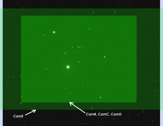
For a given optical setup, the field of view (FOV) will be determined by the physical size properties of the image sensor in the camera. Larger pixel sizes and higher number of pixels in the sensor's array will increase the FOV of the resulting image. As can be seen from the table above, the FOV of the test cameras varies quite a bit. The following image will graphically show the differences between the cameras tested. |
|
| |
|
|
| |
|
|
| |
|
|
| |
The graphic above was created by starting with a starfield image taken with the Starfish camera. The green overlay panels show the relative FOV of the other cameras using the same optical setup. The CamB, CamC, and CamD cameras all have approximately the same FOV. The CamA camera has exactly the same FOV as the Starfish since it uses the same image sensor. The CamE camera has a slightly larger FOV in the horizontal direction, but is smaller in the vertical direction. |
|
| |
|
|
| Sensitivity: |
|
| |
Signal to Noise ratio (S/N) of the resulting guide camera image is what will primarily determine the accuracy of the guide star position calculation. The light sensitivity of the image sensor is what defines the amount of signal in the image that is due to light photons arriving from the guide star.
Image sensor sensitivity is specified in many different ways by different manufacturers. The most widely used method is to specify the Quantum Efficiency (QE) parameter. This is a measure of the efficiency in which the image sensor can convert light photons into electrons that can be measured by the A/D converters in the camera. The cameras that use Sony image sensors cannot be easily compared to the others because of the way Sony measures sensitivity of their image sensors.
For our tests, I imaged the target star field using several exposure times for the picture. Exposure times were chosen to be fairly short intervals since those are typical of what is used while guiding. Longer exposures will allow you to guide on fainter guide stars but the longer exposure times will result in less frequent guide corrections being sent to the mount. Because of seeing conditions, you will usually not want to have too short of an exposure time, otherwise you will be trying to have your mount chase the apparent position of the guide star due to seeing turbulence and not the actual position of the guide star.
There is a fine balance that needs to achieved when determining the best exposure time to use for a given set of equipment and seeing conditions. Exposure durations of from 0.5 sec to several seconds are common.
In the set of pictures taken, only a single dark frame was subtracted from each picture. The resulting images were contrast stretched at approximately the same amount so as to present a consistent relative star brightness for all of the images produced by the cameras at a given exposure setting.
The pictures can be seen here: http://www.fishcamp.com/starfish/starfish_sensitivity_images.html
As can be seen form the pictures, the CamE camera is the clear winner in terms of sensitivity. This is not surprising from the QE specification for its sensor in the above table. This sensor did not have anti-blooming circuitry in it so all of the images from the CamE camera show significant blooming on all of the bright stars. You would not want to select any stars that exhibited this blooming characteristic as your intended guide star. The CamD camera was the least sensitive of the cameras tested. |
|
| |
|
|
| Noise: |
|
| |
The noise of your camera is the second primary component that will determine the quality (S/N) of your camera's images. Noise can be the result of many factors and can be manifested in different ways. The following two image animations demonstrate how noise can affect your guide images: |
|
| |
|
|
 |
 |
Starfish |
CamA |
| |
The image on the left is a sequence of several consecutive pictures taken with the Starfish camera. The image on the right is a sequence taken with the CamA camera. Both sets of pictures were taken with the same exposure time and were contrast stretched to the same degree. Since both cameras are using the same image sensor, the sensitivity of the cameras should be identical. Looking at the image on the right, however, you have a harder time seeing several of the fainter stars since they are being obscured by the noise component in the image. Likewise, the auto-guider software will have a harder time computing a star location if there is significant noise in the image.
Many times people will make a statement like "the image sensor determines the performance of a camera". Well, to a large degree, the image sensor used in a camera will determine many of the performace characteristics of a camera. However, the design of the camera electronics surrounding the image sensor can have a profound effect on performance. Seeing the two image animations above, side by side, helps illustrate the point. Both cameras are using the same image sensor but the final images produced by the cameras are quite different.
In this case, the CamA camera was designed to be a low-cost, minimalist guide camera. The Starfish camera, however, was designed as a higher-end guide solution. It has some dedicated image processing, in hardware, that detects and corrects certain dynamic noise components like the line offset variations visible in the CamA image.
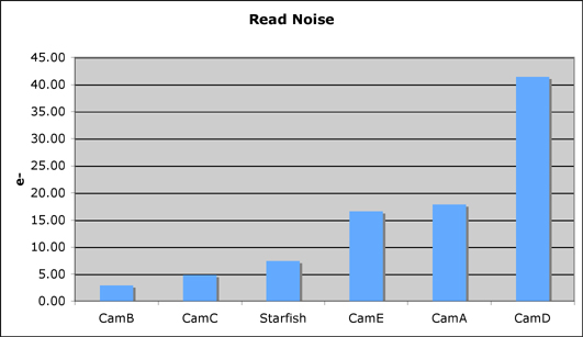
A dynamic noise measurement commonly made on cameras is a 'read noise' measurement. This is done by taking a pair of bias frames and flat frames that are then used to compute the cameras read noise. Programs like IRAF have routines (FINDGAIN) that simplify the computation of the read noise of a camera. We have measured the read noise of the cameras being tested with the following results: |
| |
Camera: |
Starfish |
CamA |
CamB |
CamC |
CamD |
CamE |
| |
Read Noise: |
7.42e- |
17.86e- |
2.89e- |
4.86e-
|
41.4e- |
16.59e- |
|
|
| |
|
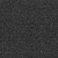
| In addition to the dynamic noise components that vary from image to image, there can be static noise components. An example of this is shown below. |
| |
|
|
|
Starfish |
CamA |
| |
|
Fixed Pattern Noise |
| |
|
The above shots are two Bias frames. The one on the left was taken with the Starfish camera. The one on the right was taken with the CamA camera. Both images are contrast stretched approximately the same. Both images are also zoomed in 400% to show the pixel structure in the image. Notice that the image on the right has an offset intensity associated with the rows and columns of the image. Alternating row/cols are brighter and darker in a repeating pattern. This ends up giving the image a checkerboard look to it. The Starfish camera has dedicated image processing hardware to detect and correct for this on the fly as the image is being captured. Notice the lack of fixed pattern noise in the image from the Starfish camera.
Fixed pattern noise is routinely eliminated by astrophotographers from their images through the process of image calibration during post capture image processing steps. However, this is sometimes not practical when using the camera as an auto-guider since the images are being exposed and operated upon in somewhat real-time. For guide applications, it is best not to have to deal with this kind of anomaly in the image. |
| |
|
|
| Guide Pulse Commands: |
|
| |
Auto-guiders work by taking a picture of a guide star, comparing the position of the star in the image relative to a reference position, and then sending a command to the telescope mount to correct any error that was detected in the star's position. The auto-guider's software knows how to correct a given error by means of a calibration routine that is executed at the beginning of the guide sequence. Basically, the calibration routine computes how much the telescope mount motors will move for a given length of a guide pulse. Guide cameras and telescope mounts use a defacto industry standard ST-4 style interface port that contains 4 guide pulse signals such that the camera can command the telescope mount to move in all four of the possible directions (North, South, East, or West). A mount movement is commanded by pulsing one of the four guide pulse signals for a desired length of time. The longer the pulse, the more the mount will move for the given correction.
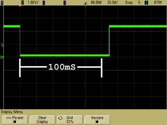
For this test, we used MaxIm DL's ability to set specific parameters of the guide camera. Specifically, we set the minimum and maximum guide move to be 100mS. This guaranteed that every guide correction made by the camera should be exactly 100mS in duration. What we discovered is that there was a lot of variability in the length of the guide pulses generated by the cameras. |
|
| |
|
|
| |
We took some oscilloscope pictures of the test results and present them below: |
|
 |
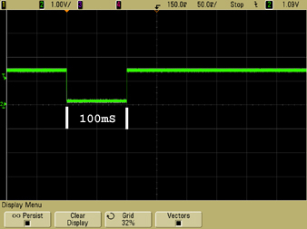
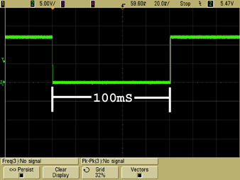
CamA - Pulse had good amplitude levels and consistency in duration. However, the pulse had a fixed offset of about 10% from the nominal 100mS pulse commanded. |
|
| |
|
|
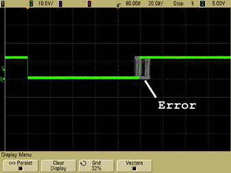 |
CamC - Pulse had good amplitude but almost 20% variability in pulse duration from the nominal 100mS pulse commanded. In addition, the pulse duration varied with processor work load. |
|
| |
|
|
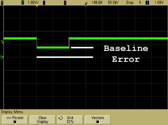 |
CamD - Pulse had poor amplitude sitting about 0.8 volts above the ground baseline level. In addition, there could be seen a slight pulse duration variability from the nominal 100mS pulse commanded. |
|
| |
|
|
 |
CamE - Pulse had good amplitude and pulse duration characteristics. |
|
| |
|
|
 |
Starfish - Pulse had good amplitude and pulse duration characteristics. |
|
| |
|
|
|
| |
In the scope pictures above, a digital sampling scope was set to infinite persistence on its display so that multiple guide commands were overlaid on top of each other. Approximately, 100 guide command pulses were recorded in each image. That way any variability in pulse duration or amplitude between commands would be readily visible.
CamA, in general, had good pulse characteristics. Levels were good and the pulse duration was consistent from command to command. However, there was a peculiar duration offset of about 10% visible. Each pulse command had the exact same offset added to it giving the pulse a duration of ~110mS vs the desired 100mS nominal pulse width.
CamB was not tested since it did not have a built in guide port.
CamC had the most variation of the cameras tested. The pulse duration varied wildly based upon processor load. As a matter of fact, just moving the mouse around the screen while guiding caused a noticeable variation in pulse width from nominal.
CamD had good pulse width repeatability but had a peculiar amplitude offset. Ideally, a pulse signal should be driven to the ground reference level to register a guide command. In this case, the guide signal would only go to 0.8V above ground level. It is not certain if any telescope mounts would have a problem with this. If the mount controllers utilized standard TTL logic levels on the guider interface, this would be precariously close to the TTL logic level low signal level which could , perhaps, cause uncertainty in the command state of the signal.
The Starfish camera and CamE both had excellent pulse characteristics. The Starfish camera has on board pulse generation hardware that guarantees consistency in pulse duration from command to command. It actually has four such sets of hardware so that each guide direction signal can operate independently and concurrently with the other directions. This is important if you have a mount that can handle simultaneous guide commands in multiple directions. |
|
| |
|
|
| |
|
|
Copyright © 2009. All rights reserved. |
|